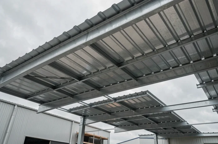
The design of a flat roof steel deck frame is not just about laying corrugated sheets on purlins. The sizing involves compliance with the DTUs, the durability of the waterproofing, and, above all, the validity of the ten-year warranty. Here, we detail the technical points that most installation guides overlook.
DTU 40.35 and DTU 43.3: the normative framework that conditions the ten-year warranty
A flat roof steel deck falls under two distinct unified technical documents depending on the function of the sheet. The NF DTU 40.35 regulates coverings made of corrugated sheets: it sets the minimum slopes based on the rib height and imposes anti-condensation measures in the wall.
When the steel deck serves as a load-bearing element for a rooftop terrace (with an applied waterproofing system), it is the NF DTU 43.3, supplemented by the CSTB 3537-V2 guide, that applies. This reference covers areas with low to high humidity and details the fastening constraints of the deck on the frame.
Failure to comply with either of these DTUs can lead to the forfeiture of the craftsman’s ten-year warranty and the insurer’s refusal to cover claims in the event of a disaster. We recommend verifying, before signing the quote, that the frame-covering lot explicitly mentions the relevant DTUs.
To delve deeper into the reading of a flat roof steel deck frame diagram, it is essential to keep in mind that each dimension of the plan (spacing of the purlins, overhang, slope) directly stems from these normative requirements.

Sizing of purlins and spacing: the calculation parameters of a flat roof frame
The frame of a flat roof rests on purlins, usually made of wood (beams) or steel (IPE, HEA). The choice of material depends on the clear span and the loads to be supported.
Permanent loads and climatic loads
The structure must support the dead weight of the steel deck, insulation, waterproofing system, and, if applicable, vegetation or accessible decking. In addition, climatic loads are added: snow (variable depending on the geographical area and altitude) and wind (pressure and suction).
The spacing of the purlins determines the overall strength of the roof plane. A spacing that is too wide causes excessive deflection of the steel deck under load, leading to water retention and mechanical fatigue of the fasteners. The tables provided by manufacturers of corrugated sheets give the maximum allowable spacing based on the chosen profile, sheet thickness, and applied load.
Minimum slope and rainwater drainage
A so-called “flat” roof is never horizontal. The commonly accepted minimum slope is between 2 and 5%, created either by the geometry of the frame (purlins of decreasing heights) or by added slope wedges. Insufficient slope promotes stagnation, accelerates the degradation of waterproofing, and falls outside the scope of the DTUs.
Fixing the steel deck to wood or steel frames
The connection between the steel deck and the load-bearing structure determines wind resistance and the durability of the covering. There are two main configurations.
- On a wood frame (laminated or solid purlins), fastening is done using self-drilling screws with EPDM sealing washers, screwed at the top of the rib for accessible roofs or at the bottom of the rib according to the applicable DTU.
- On a steel frame (IPE/HEA purlins), self-drilling screws with wings penetrate the base of the profile. The tightening torque must be controlled to avoid crushing the sealing washer or deforming the sheet.
- In both cases, the number of fasteners per square meter increases at the edges and corners of the roof, areas subjected to the strongest wind suction. The layout plans provided by the manufacturer specify this increased density.
Undersized edge fastening is the primary cause of steel deck detachment during storms. We regularly observe claims related to layouts that do not comply with the wind zones defined by the Eurocodes.
Insulation and vapor barrier: avoiding condensation under the steel deck
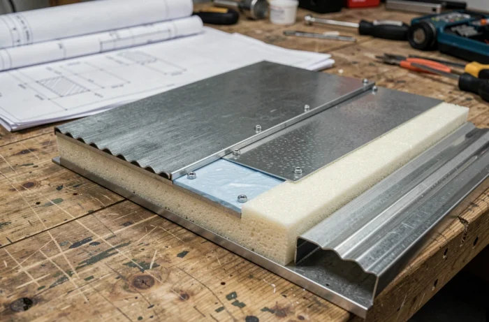
The steel deck is a vapor-tight material. Without an appropriate device, vapor produced by indoor activities migrates to the cold underside of the sheet and condenses. This phenomenon degrades the insulation, corrodes the fasteners, and generates visible streaks.
The solution lies in the installation of a continuous vapor barrier on the warm side, beneath the insulation. The Sd (equivalent diffusion thickness) of the vapor barrier must be adapted to the humidity of the room. For a high-humidity room (communal kitchen, swimming pool), a metal vapor barrier is required.
The insulation itself, placed between the purlins or above the deck in a “warm roof” configuration, contributes to controlling the dew point. In a warm roof, the insulation is placed above the load-bearing steel deck, covered by the waterproofing membrane. This configuration eliminates thermal bridges at the level of the purlins and simplifies the continuity of the vapor barrier.
- Cold roof (insulation under the deck): mandatory ventilation of the air gap between insulation and deck, suitable for unheated buildings or those with low humidity.
- Warm roof (insulation on the deck): preferred solution for inhabited spaces, compliant with DTU 43.3 with load-bearing element in corrugated steel sheet.
- Inverted roof (insulation above the waterproofing): rarely used with steel decks, reserved for specific cases of accessible roofs with heavy protection.
Roof safety and lifeline: an often-overlooked requirement
Any accessible flat roof for maintenance (cleaning drains, maintaining waterproofing) must include fall protection devices. Regulations require peripheral guardrails or, failing that, lifelines compliant with EN 795 standards fixed to the load-bearing structure.
The anchor points are not fixed to the steel deck alone: they penetrate the sheet and are bolted to the purlins or to plates welded to the metal frame. This detail must appear on the frame diagram from the design phase, as a later addition requires penetrations that compromise waterproofing.
The frame of a flat steel deck roof is designed as a complete system, from the vapor barrier to the lifeline. Each layer depends on the previous one, and the sizing of the load-bearing structure conditions the compliance of the whole. A detailed diagram, validated by an engineering office, remains the best tool to coordinate the lots and secure the ten-year warranty.